G-code, Explained
What it is and how to use it
G-code and 3D Bioprinting
In extrusion-based 3D bioprinting, G-code is useful for creating complex and intricate tissue models by providing precise instructions. A G-code file is generated from a model of your desired motif. For 3D bioprinters, it may be a biological structure. The model is sliced into thin layers by slicing software which generates G-code commands for each of these layers.
The G-code commands control the bioprinter’s movements, ensuring that the print- or toolhead can move to the correct position to deposit bioinks or crosslink already extruded material accurately. The commands also instruct the print- or toolhead to turn on/off, and for how long, effectively controlling the amount of bioink to deposit and where. This is important to maintain the integrity and viability of printed cells and tissues.
By integrating G-code, 3D bioprinting achieves the precision and control needed to create functional biological models that have the potential to advance fields like tissue engineering and regenerative medicine.
Understanding G-code
At first glance, a G-code file can appear complex and intimidating. But it is an easier language to understand than it first appears. When you break it down, the numbers and commands are simply instructions related to cartesian coordinates (X, Y, Z) and other machine operations.
To understand it better, let us look at the commands usually used in a typical line of G-code:
G## X## Y## Z## F## E##
Command Basics
Each letter has a specific meaning that is important to understand when building or editing your G-code. If any letter is omitted, the value stays the same as the previous row.
G: General Command
For example, G1 is an “absolute-move command” which tells the print- or toolhead to move in a straight line to the specific position defined next.
X:
Defining the position on the X-axis (horizontal) to move to.
Y:
Defining the position on the Y-axis (horizontal) to move to.
Z:
Defining the position on the Z-axis (vertical) to move to.
F: Feed Rate
Determining the speed at which the printhead will move in mm/min.
E: Extruder or Tool Offset
Controlling the extruder of the print- or toolhead.
Other relevant G-code commands include:
T: Tool Selection
In our BIO X Series, this would allow for the selection between 1 to 6 tools.
M: Machine Commands.
It controls how the machine functions.
Example: G-code Breakdown
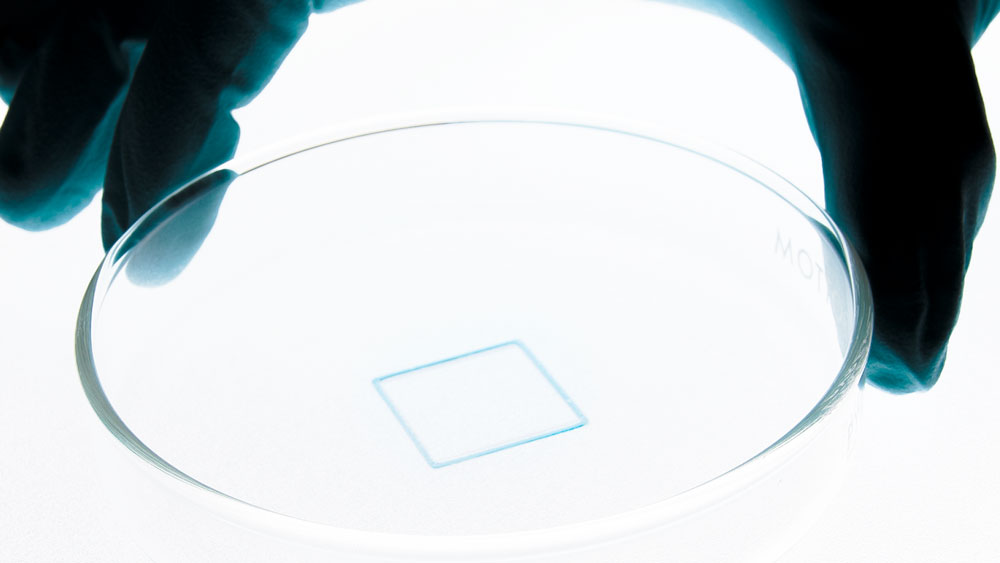
Let’s breakdown a basic G-code example that prints a small square with 20×20 mm dimensions on the BIO X6 3D bioprinter.
					G90
G21
M83

T0
G1 Z0.4 F4800
G1 X10 Y10 F1200
G1 X-10 E1
G1 Y-10 E1
G1 X10 E1
G1 Y10 E1

G0 Z30
M84
G-code Commands:
G90: Defines the absolute coordinates that the machine will be operating in.
G21: Sets the units to millimeters for easier control.
M83: Telling the machine to operate the printhead from its last position, not from a fixed origin.
Tool Selection:
T0: Refers to which printhead to use and places it in active position.
Movement Commands:
G1 Z0.4 F4800: The G1 command initiates linear movement. In this case, the printbed will move to the vertical Z-axis at 0.4 mm below the nozzle of the printhead (T0), at a speed of 4800 mm/min.
G1 X10 Y10 F1200: This tells the printhead to move to the coordinates X10, Y10 at a speed of 1200 mm/min.
G1 X-10 E1: The extruder moves from X10 to X-10 and extrudes (E1) the bioink as it moves. The subsequent G1 commands continue to define the movement of the extruder to create a square shape, with extrusion occurring on each line.
End Commands:
G0 Z30: The G0 command initiates rapid movement, to a Z-axis of 30 mm. This lowers the printbed below the printhead to avoid it interfering further with the print.
M84: Finishes the current operation.
How CELLINK handles G-code
DNA Studio 4: The G-Code Editor
With DNA Studio 4, we have simplified the workflow of G-code for 3D bioprinting applications. By reducing the complexity, we can bring advanced bioprinting to more researchers, effectively removing the barrier of entry.
DNA Studio 4 enables you to easily export a G-code file from an .STL, or to edit your own G-code file directly in the software’s editor.
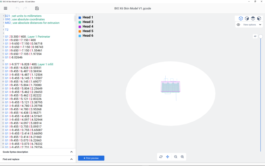
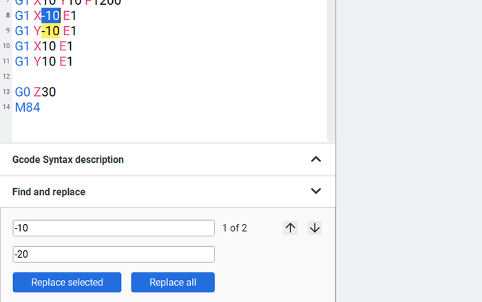
Within the G-code Editor, you can visualize how your BIO X or BIO X6 will move and follow the toolpath on screen. This way, you can track the changes to the code in real time, ensuring a successful print every time. Additionally, our Find and Replace feature will expedite your debugging processes by allowing you to make multiple changes in one fell swoop.
Preview mode
Find and Replace
CELLINK customers have access to a more extensive guide in our Knowledge Center, along with more useful guides and tutorials that help in other parts of the 3D bioprinting journey.


